

Concorde
Case Study
To be counted among the greatest engineering marvels of the twentieth century, Concorde’s story, like so many technological achievements in that century, ended in tragedy.
We have conducted a detailed investigation into the aircraft’s structural design, celebrating the innovation it required and scrutinising the elements which led to its infamous downfall.
It is a mark of their status as aviation icons that retired Concordes are not to be found among the rows of metal carcasses left to decay in aircraft graveyards, but raised on plinths and pedestals to be admired and maintained as museum pieces.
Introduction
Not only was Concorde an engineering marvel, but prior to the infamous Paris disaster of July 2000 it could be counted among the safest operational passenger airliners in the world, with zero passenger deaths-per-kilometres travelled. But the joint project—a “concord” between the French and British governments—proved a commercial failure, and it is no coincidence that the civil aviation industry has not been inclined to pursue supersonic commercial flight further in the years since Concorde’s final voyage in 2003.
Interest in faster-than-sound, trans-oceanic passenger jetliners has piqued again in recent years, however. And as focus has been pushed to the boundaries of space, where cruising altitudes can be described as “sub-orbital” and the promise of weightlessness is included in the fare, a tension in the industry is being exposed.
While the line between aircraft and spacecraft has become increasingly blurred since 1969—the year which saw Concorde take off from Toulouse for its maiden flight and Apollo 11 touch down on the moon—today’s twin concerns for space and sustainability look to be causing a fracture in the civil aviation industry. While such ventures as Virgin Galactic have shifted to rocket propulsion to achieve point-to-point Mach speed travel, others, like Wright Electric, are pulling in the opposite direction in their attempts to electrify subsonic commercial airliners. The niche once filled by Concorde is notably absent.
Like Concorde, however, the new supersonic ventures can pitch each successful take-off as an historico-cultural “event”. But this phenomenon should be short-lived, since, if these companies are to revolutionise flight and effect large-scale market change, they will have to establish supersonic travel use as a cultural norm, as a go-to method for point-to-point travel that is affordable, scalable, sustainable, and profitable. It remains to be seen whether the results of their efforts will find a plinth next to Concorde, or else be committed to the scrapheaps of history.
Only twenty of the Concorde were completed, including two prototypes and two pre-production units.
Technical Specifications
Crucial in the manufacturing of the aircraft was the machining or milling of components from solid billets of Hiduminium RR.58 alloy. With impressive fatigue tolerance at temperatures in excess of 120°C, the 2.5% Copper-Aluminium RR.58 alloy was used for 95% of Concorde’s structure, with steel and titanium used in specific applications.
As Computer Numerical Controlled (CNC) machines were not yet in common use, non-reprogrammable tape-controlled machines were employed to carve components in the ‘dug-out canoe’ method. Highly accurate and able to do away with fixtures, machining in this way returns a high strength-to-weight ratio, offering greater structural integrity by avoiding the high stress areas left by welds and rivets. The machining process produces huge amounts of waste, however, and is therefore very costly; though it allows for some recycling of materials, this is only possible if the material is not too contaminated with cutting compounds and other metals. But this method of machining otherwise proves especially advantageous when a structure is to undergo significant thermal expansion. Useful, since when travelling at speeds in the Mach numbers, increases in temperature saw Concorde grow in length by as much as 0.3m.
Concorde was powered by four Olympus 593 turbojet engines, manufactured by Rolls-Royce Ltd, Bristol (Engine division), with afterburners manufactured by SNECMA, Paris, the addition of which raised the engines’ power beyond the output specification, from 32,000lb to 38,000lb of thrust.
This increase in power allowed for improvements in landing and take-off performance, with a 15.5% increase in wing area, enabling greater fuel capacity. The extra fuel load increased the Maximum Take-Off Weight from 158,750kg to 166,490kg, however, and this had major implications for the aircraft’s structure. As a result, the maximum structural temperature had to be reduced by 26 Kelvin, to ensure the increased load did not affect the target 45,000 hours for the airframe lifespan. The max cruise speed also had to be reduced, from Mach 2.2 to Mach 2.0, increasing the London to New York leg by some 5 minutes.

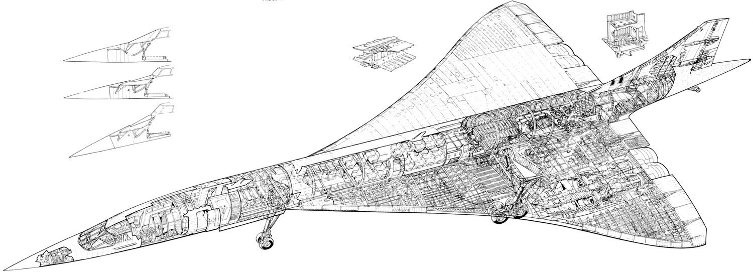
Concorde’s wing is a cantilever, low-wing delta planform monoplane. It has a low aspect ratio of 1.7 and a very thin thickness/chord ratio of 3% at the root and 2.15% around the engine nacelles, providing as low a profile drag as possible. The wing has continuous camber, varying incidence, and a slight anhedral, designed to reduce drag and increase stability at sub- and super-sonic speeds. With the flight characteristics of its anhedral delta wing, many pilots described Concorde as being closer to tactical fighter jets than a civil aircraft.
The forward wing rib construction, shown in the image, demonstrates the use of machined RR.58 in different arrangements: an open hoop construction, crack stopping stringers and cut outs, and hoops with internal pin jointed triangulated bracing.
Given that the wing has such a thin thickness/chord ratio, and considering the substantial pressure forces encountered in supersonic flight, a high strength, multispar structure is used in the main wing, an arrangement in which the spars and ribs are closely pitched.

The wing structure on Concorde is indeed very complex, with spars and ribs alternating between RR.58 machined and RR.58 tubular lattice webs, serving to conserve weight where the extra strength of machined components is not required. The eight main rear spars that are incorporated into the fuselage frames provide the support for the main wing. These components extend between the engine nacelles on each main wing providing a very strong and stiff structure. Each spar consists of a top and bottom girder and web, but is machined as one.


Overseen by an Anglo-French government committee, the engineers faced numerous design challenges arising from the target capabilities of the aircraft.
For example, the supersonic design of the wing meant that for Concorde to perform the slow landings which are required by civil passenger aircraft (190 to 165 knots) it would have to approach at an angle of attack of 12.5 degrees. Due to its pointed nose (a shape required for supersonic flight performance), it was necessary to incorporate a hydraulic drooping mechanism, allowing the nose to be lowered upon take-off and landing, thereby improving visibility for the pilots, whilst a hydraulically operated visor was required to provide both clearance for the nose and suitable aerodynamics during flight.


A less noticeable feature of Concorde is the small size of the cabin windows. This is due to the altitude at which the aircraft flies, which must be high to achieve optimum efficiency at Mach 2. At 60,000ft Concorde encounters a pressure 3.5 less than a normal civil aircraft encounters at 35,000ft.
Despite their reduced size, the windows cut outs nonetheless produce stress concentration areas, and so a long machined RR. 58 window panel runs the length of the cabin to provide extra strength. Triple-gap windows are also used to provide greater thermal insulation and reduce the pressure in stages, decreasing the local stress on each pane of glass.

Following the Paris incident, in which a tyre explosion fired rubber fragments into the left wing’s fuel tanks which leaked heavily and subsequently ignited, much attention has been given to this element of Concorde’s design.
There are nineteen individual fuel tanks on Concorde: four tanks in each main wing, one in each outer wing, and two in the in the centre of the fuselage under the cabin floor. The trim tanks include two in each forward wing, one in the tail, and two in the forward fuselage.
The tank walls consist of machined RR.58 corrugated webs that allow large temperature fluctuations in the wings, from around -50°C (due to altitude) to 120°C (from friction). The fuselage tanks have stressed upper and lower skins that are designed to withstand an upward impact of 15Gs.

The large trim tanks perform a very specific role in Concorde. When the speed of the air moving over an aircraft’s wing increases past Mach 1, shock waves form. These shock waves can create a shift in the centre of pressure and therefore produce a pitching down moment.
Concorde’s wing designers did their best to reduce this phenomenon, commonly known as ‘Mach tuck’, but there was still a shift of about 2 meters rearwards.
Rather than counteract this affect with trim tabs (which would have caused a dramatic increase in drag), fuel was distributed between large forward and rear trim tanks continuously during flight. This shift in the centre of gravity effectively acted as an auxiliary trim control.
When a tank was ruptured in the catastrophic Paris fire, the fuel was set alight resulting in the melting of the Hiduminium wing structure and total loss of control of the aircraft. After the Paris fire, various airworthiness requirements were issued, one of which was the restriction of flow from a possible punctured hole. It was decided that a similar system to that used in wartime fighter aircraft should be implemented: a system incorporating rubber liners which, once punctured by shrapnel or bullets, would partially reseal.
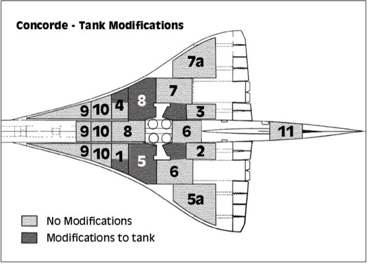
Concorde’s liners also incorporated Kevlar for extra strengthening. As the modification could have involved adding a substantial amount of weight to a very weight sensitive aircraft (fuel distribution being used for trim) the Kevlar-rubber liner panels were designed to have exactly the same density as kerosene. This meant that the liners would directly displace some fuel therefore reducing the overall range of the aircraft but not changing the aircraft’s weight distribution.
Following the incident, various airworthiness directives were put to the Concorde manufacturers for it to regain airworthiness status.
The directives were issued by the CAA and the DGAC (the French civil aviation authority) on 5th September 2001 and included: leak flow rate reducing fuel tanks, reduction and armouring of possible electrical ignition sources to prevent sustained fire, new tyres, and flat tyre detection and warning system checks.
Future Developments
It is a great shame that such an aeronautical engineering marvel has ceased to fly in service. There were, however, planned developments of Concorde that started just four months after its entrance into service in 1976. The Concorde ‘B’ model, although never actually produced, was heavily explored, and a study into possible upgrades began in the early 1980s. The plan looked to ensure that the demands for supersonic air transport were met and that the Anglo-French project would still be the main contender (at the time of Concorde’s launch, the fault ridden Soviet Tupolev Tu-144 was the only other supersonic civil aircraft in operation).
The objectives were to make the aircraft more airline and manufacturer friendly. Airlines would receive performance improvements with not only longer range and better fuel consumption but, having ditched the noisy and uneconomical afterburners, the ability for the aircraft to be used on more flight paths across Europe, Australia, America, and Japan, incorporating trans-Pacific flights.
The main upgrades included a larger and drooping leading edge and increased wing with enlarged outer wings. This made for better take off, landing, and subsonic cruise characteristics. The extra lift produced by this ‘new’ wing would allow for the aircraft to fly at lower angle of attack, therefore requiring slightly less thrust from the engines and reducing fuel consumption. The leading edge droop incorporated different operating positions for optimum performance. From what information can be found on the ‘B’ the aircraft’s structure itself remained otherwise unchanged.

The engines would have been upgraded, too, with larger diameter LP compressor and an LP turbine with an extra stage making it a twin-stage turbine. This upgrade would result in significant increases in air flow, and therefore thrust, with claims of 25% greater airflow on takeoff. The thrust gains of the new engine at takeoff and transonic speeds would have overcome the need for afterburners which consumes huge quantities of fuel. This also reduced the noise levels produced by the powerplants but further steps were taken by installing noise reducing ducts in the intake and exhaust.

Technical images sourced from Jane’s All the World's Aircraft (2004, Jane’s Publishing)
Closing Thoughts
Our technical interest in Concorde is threefold: for its engineering and technological innovations; for the nature of the partnerships involved; and to reflect on its commercial performance. A monument to collaborative engineering, but with a complicated and ultimately tragic story, much can be learned from the aircraft and its life in each of those areas. We also have an interest in the mechanics of flight more generally, however. While Hooper Quinn has worked on several aviation projects, our founder holds a pilot’s licence and builds and flies paramotors.
To be explored further in our case study on the Innovations of the 21st Century, we are particularly intrigued by the future of supersonic commercial travel, including the underlying industrial and societal tensions described at the top of this article, the technical innovations it will require, and the economic and environmental impacts of the commercial direction the market selects for it.
With NASA and Lockheed Martin already working on an experimental supersonic craft—the X-59 Quiet-SST—which reduces the 105dB sonic boom to a 75dB “sonic thud”, we could be on the verge of a resurgence of Concorde-like designs. But such designs will face compelling competition from a handful of radically different, sustainability driven ideas, such as the manta ray inspired “Blended Wing Body” of the Boeing X-48.
One hundred years on from the world’s first commercial flight, aviation looks poised again to make several more radical changes to our world in the next century.

Bring your idea to life with exceptional engineering
Our robust design, test and build procedures ensure that your product's development journey follows a well-trodden path maintained to the highest standards from start to finish.

Accelerate your technology towards quality solutions
Our engineering team offers a uniquely competent resource to help companies understand, solve and demonstrate their unproven technological and scientific innovations.

Contact us
If you have a product or technology that you want to develop, we want to hear from you
How it works
Send us an enquiry using the form
Our team will quickly get up to speed with your project and invite you for a free initial consultation to discuss your requirements
We will prepare a full technical proposal outlining to get your project to where it needs to be.